Motion Replicator
|

|
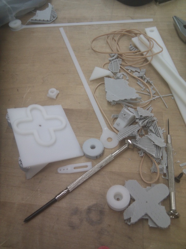
This was a one-man project completed over the course of three weeks during winter break of 2012-13. Inspired by the engineering marvel that is the da Vinci Surgical System, I wanted to create a robotic arm that would track a point specified by a human hand. All parts were designed by myself and modeled in SolidWorks. The arm is 3D printed out of ABS plastic, and the base and the tracking stage are made from 1/8" polycarbonate. The project's components and operation are outlined below.
Point Tracking:
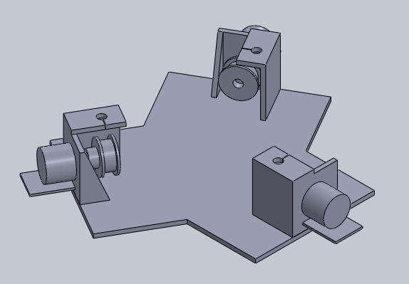
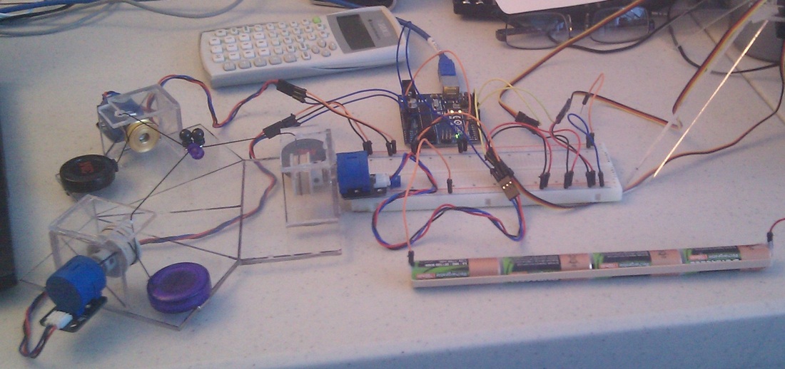
The "sensing" or "tracking" stage, shown above on the second row, allows the user to pull three strings tied together at the "target point". The strings rotate with timing belt pulleys which are secured to multi-rotational potentiometers, thus tracking the lengths of the strings. The potentiometers in turn send analog signals to an Arduino Uno which calculates the x-y-z coordinate of the target point from the string lengths.
Motion Replication:
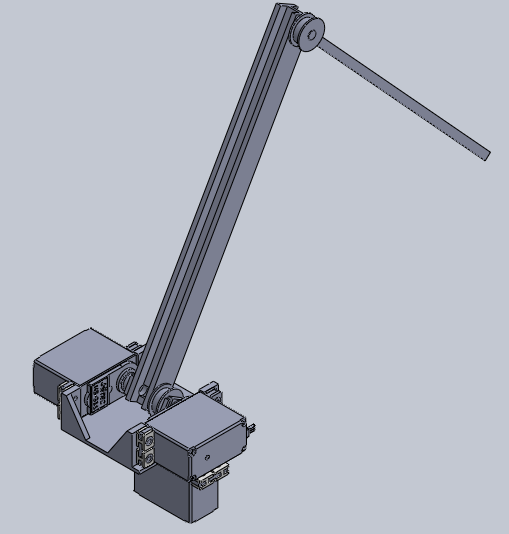
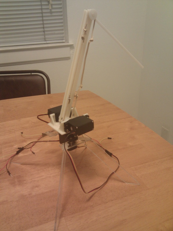
The arm stage is a double-jointed, three degree of freedom robotic arm actuated by three servos. The arm replicates the motion of the target point by continuously pointing at the x-y-z coordinate relative to its own coordinate system. From the target point coordinates, the Arduino calculates what three servo angles are necessary to achieve the arm position for that moment in time.
Point Tracking:
The "sensing" or "tracking" stage, shown above on the second row, allows the user to pull three strings tied together at the "target point". The strings rotate with timing belt pulleys which are secured to multi-rotational potentiometers, thus tracking the lengths of the strings. The potentiometers in turn send analog signals to an Arduino Uno which calculates the x-y-z coordinate of the target point from the string lengths.
Motion Replication:
The arm stage is a double-jointed, three degree of freedom robotic arm actuated by three servos. The arm replicates the motion of the target point by continuously pointing at the x-y-z coordinate relative to its own coordinate system. From the target point coordinates, the Arduino calculates what three servo angles are necessary to achieve the arm position for that moment in time.
Design Details
Electrical/Code:
- Controlled by Arduino Uno (code can be found here)
- Target point is tracked by three multi-rotation potentiometers
- Low-pass filter to reduce potentiometer signal jitter
- Target point and servo angles are calculated by sphere or circle intersection math
- Three servos are controlled by PWM and powered from AA batteries
Mechanical:
- Tracking stage:
- Strings are wrapped around timing-belt pulleys with rubber bands for traction
- Potentiometers are multi-rotation, allowing up to 10 revolutions
- Strings are from retractable lanyards
- String origins are along x- and y-axes on an equilateral triangle
- Arm stage:
- Arm is 3D printed out of ABS plastic, stand is cut out of 1/8" polycarbonate
- Shafts and holes have 0.4 mm tolerance for rotation
- Lower arm has I-beam shape to resist anticipated bending
- Added 3 mm radius fillets for strength
- Rubber band transfers angle from bottom servo to upper arm
- Used rubber bands instead of timing belt for flexibility
- Lots of knots for just the right length for appropriate traction and tension
- Three Hitec HS-311 servos
- Arm is 3D printed out of ABS plastic, stand is cut out of 1/8" polycarbonate
